
Speaker
Description
Electrothermal Modelling of Totem-Pole PFC Converter
P. Górecki , M. Strąkowska , R. Olbrycht , R. Kasikowski *
* Łódź University of Technology, Institute of Electronics, 211/215 Wólczańska Str, 90-924 Łódź, Poland, rafal.kasikowski@p.lodz.pl
** Gdynia Maritime University, Department of Ship and Industry Automation, 81-87 Morska Str, 81-225 Gdynia, Poland, p.gorecki@we.umg.edu.pl
Abstract
1.Introduction
Power converters, due to their nonlinear load characteristics, generate significant mains harmonics, necessitating power factor correction (PFC) to prevent power quality degradation. PFC, usually in the form of dedicated modular circuitry, adjusts the input current waveform to align in phase and shape with the input voltage to achieve a high power factor. The latter, along with power conversion efficiency, remains a key performance parameter of current designs. The Totem-Pole topology (Fig. 1) combines the advantages of traditional PFC topologies with the elimination of the diode bridge rectifier and naturally facilitates the use of high-performance gallium nitride (GaN) transistors. The power loss generated in converters can be predicted using SPICE-based models that employ the electrothermal analogy to represent thermal phenomena with electrical equivalents.
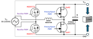
Fig. 1 Totem-pole PFC topology.
2.Electrothermal modelling framework
Circuit-level simulations of power converters serve as an effective tool in optimizing their design process. Accurate predictions of losses across all components facilitate optimal selection of switching frequency and suitable components. To confirm the applicability of the components in the design, their temperatures are calculated over the range of planned operating conditions. A primary challenge in electrothermal circuit-level transient simulations of power converters arises from the substantial disparity in time constants. The shortest, which determines the maximum simulation time step, corresponds to the rise and fall times of the power transistors used and is on the order of a dozen nanoseconds, whereas the longest, which determines the simulation duration, represents the longest significant thermal time constant. For PCB assemblies where free convection prevails in thermal dissipation, this duration can attain several kiloseconds. Consequently, performing electrothermal simulations within reasonable time requires dedicated methods and multiple simulation programs.
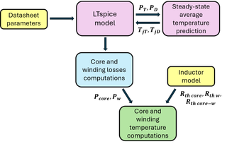
Fig. 2 Block Diagram of Electrothermal Modelling Framework.
LTspice served as the primary simulation program (Fig. 2). To address time constant disparities in the simulated converter, a segregated iteration method was employed: after every three input voltage periods, component temperatures were updated via the .IC command, with simulations repeated until results following three periods varied by no more than 1°C from initial values. The computations of approximate steady-state temperatures were performed in MATLAB using the average values of power dissipated in all components computed in LTspice and their Rthj−a thermal resistances. As input data for the simulations, all electrical parameters were estimated solely from the datasheets of the components used, while the thermal parameters were estimated using FEM modeling and datasheets.
3.Conclusion
In the full paper, simulation results are compared with measurement data. The temperatures of all power components predicted by the proposed model are validated against thermographic measurements performed on the investigated converter (Fig. 3).
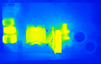
Fig. 3 Thermal image of investigated totem-pole PFC converter.
4.References
[ 1 ]. Z. Liu; F. C. Lee; Q. Li; Y. Yang, Design of GaN-Based MHz Totem-Pole PFC Rectifier, IEEE Journal of Emerging and Selected Topics in Power Electronics, Vol.4, No. 3, pp. 799 – 807, 2016, DOI: 10.1109/JESTPE.2016.2571299.
[ 2 ]. N. Mohan, W. Robbins, T. Undeland, R. Nilssen, O. Mo, Simulation of Power Electronic and Motion Control Systems—An Overview, Proceedings of the IEEE, vol. 82, no. 8, pp. 1287-1302, 1994, DOI: 0.1109/5.301689.
